Information Technology Reference
In-Depth Information
This
P
32
/
80
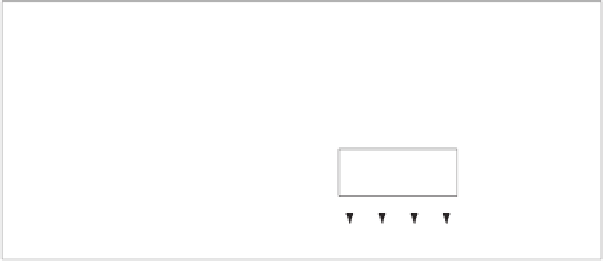
-box consists of five layers of 16 parallel elementary
P
2
/
1
-boxes
with some fixed connection between layers. Design schemes of the boxes
P
2
/
1
,
P
4
/
4
and
P
8
/
12
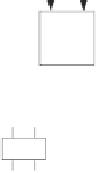
are shown in Fig. 2.
P
2
/
1
-box is controlled by one bit
v
.If
v
=1,
it swaps two input bits, otherwise (if
v
= 0) does not.
v
P
2/1
P
2/1
P
2/1
P
2/1
P
2/1
P
2/1
P
2/1
P
2/1
P
4/4
P
4/4
P
2/1
1
0
(a
)
(b
)
(c
)
Fig. 2.
Structure of the boxes (
a
)
P
2
/
1
,(
b
)
P
4
/
4
and (
c
)
P
8
/
12
2.2
Encryption Scheme
Encryption scheme is defined by the following formulas:
C
=
F
(
P, K
), where
P
is the plaintext,
C
is the ciphertext,
K
is the secrete
key(
P, C
64
,K
256
) and
F
is the encryption function.
∈{
0
,
1
}
∈{
0
,
1
}
. . .
x
63
x
64
x
1
x
2
x
3
x
4
x
1
x
2
x
3
x
4
. . .
x
63
x
64
v
32
v
1
v
2
v
1
v
2
v
32
P
2/1
P
2/1
P
2/1
P
2/1
P
2/1
P
2/1
. . .
. . .
y
63
y
64
y
1
y
2
y
3
y
4
y
1
y
2
y
3
y
4
y
63
y
64
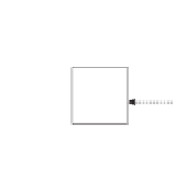
(a)
x
y - inversion (y=x 1)
(b)
Fig. 3.
(a)
IT
and (b)
FT
Secret key
K
is extended into subkey streams by simple and repeated meth-
ods. The encryption algorithm
F
is designed as sequence of the following pro-
cedures:
initial transformation IT
, 12 round with procedure
Crpyt
and
final
transformation FT
.
IT
and
FT
are simple transformations performing based on
CP
-box with control vectors. Fig. 4.(a) shows the general encryption scheme.
IT
and
FT
are constructed with 32
P
2
/
1
boxes. The left half and right half of
output of
IT
are the arrangement of those of input of
IT
xored with 0
x
55555555,
respectively.
FT
is the inverse of the procedure
IT
. Fig. 3 depicts the
IT
and
FT
.