Image Processing Reference
In-Depth Information
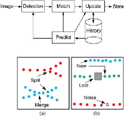
Fig. 9.6
The
predict-match-update
tracking framework
Fig. 9.7
(
a
) Illustration of
merged and split objects.
(
b
) Illustration of noise, new
object and lost objects
segmentation algorithm might fail resulting in an object being lost and/or new ob-
jects appearing. All these issues might occur simultaneously clouding the matter
further. In Fig.
9.7
some of these phenomena are illustrated. In Fig.
9.7
(a) we have
a situation where one object is occluded by another object when entering the im-
age's field of view. This continues until they split into two objects. We also see a
situation where two objects merge into one and later split into two objects again. In
Fig.
9.7
(b) we first see a situation where a new object is detected in the middle of
the scene and below a situation where an object disappears behind a static object in
the scene before reappearing again. Last we see a situation where the detection of an
object is incorrect resulting in the predicted object being lost and three new objects
appearing.
One approach for resolving these issues is to measure how many of the detected
objects are within each predicted ROI. In Fig.
9.8
(a) we show an example where we
have predicted five objects and detected five objects.
The zeros and ones in the table in Fig.
9.8
(b) indicate if a detected object is within
a predicted object's ROI. The numbers in the row (green) and column (red) outside
the table indicate the sum of a particular row or column. Entries in the table those
row and column sums are both one, have a unique match and can be assigned to each
other. This will give that object 1 is assigned to trajectory B and object 2 to trajec-
tory A. The row sum of the detected object 5 is equal to 0 meaning that this is a new
object. The column sum of the predicted object E is 0 meaning that object E is lost.
Next we look at non-assigned predicted objects with a column sum equal to 1 and
assign these objects. In our example this will mean that detected object 4 is assigned
to trajectory D. We therefore set entry
(C,
4
)
0 in the table and can now assign
object 3 to trajectory C since both its row and column sums are one. The final result
for this image is shown to the right in Fig.
9.8
(b). Looking at Fig.
9.8
(a) it might be
reasonable to assume that object 5 should be assigned to trajectory E. We can handle
such situations by increasing the size of the ROI, but this is a dangerous path to fol-
=