Image Processing Reference
In-Depth Information
4.2 Experiments type-II with echographic traces measured from an ultrasonic
prototype
The type-II experiments are based on real ultrasonic echoes measured from an isolated-flaw
(hole drilled in a plastic piece) with a multi-channel ultrasonic prototype designed for this
kind of tests in laboratory. The two array transducers are disposed in a perpendicular angle
and the square plastic piece with the hole are inside and in contact with the radiation area of
arrays. There are 4 broadband elemental transducers in each perpendicular array, 8 in the
whole system. Transducers work in the 4 MHz frequency band range. The dimensions of the
emitting surface of each individual transducer are 6x6 mm, being 24 mm the total length of
both arrays. Then, the area of the methacrylate piece to be inspected by the ultrasonic
system is 24x24 mm. Arrays manufacturing was ordered to the Krautkramer company. The
methacrylate piece has a drilled cylindrical hole in a position similar as used in experiment
type I. Then, simulations of experiment type-I are almost coincident with real measurements
of experiment type-II. The main difference is that methacrylate generates a very low level of
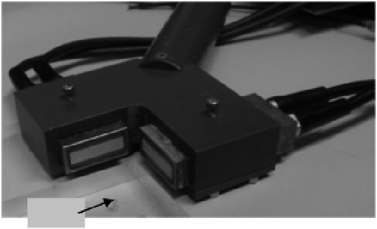
ultrasonic grain noise. Figure 6 shows the disposition of transducers and inspected piece.
hole
Fig. 6. Perpendicular array transducers and the inspected plastic piece with the hole.
In all the measurement cases, the transducers are driven for transmission and selected for
echoe reception in a sequential way. We deal with near field radiations and only one
transducer emits and receives at the same time, in our eight-shots successive measurement
process. Thus, among all the echoes produced by the isolated reflector in each transducer
shot, only those received in the two transducers located in front of the reflector (at the
perpendicular projections of the flaw on the horizontal and vertical apertures) will be
captured, because, in each shot, the echoes acquisitions are cancelled in the other seven
transducers. Additionally, these two transducers in front of the reflector could receive
certain amount of noise. And under these conditions, the rest of transducers of the two array
apertures, in each plane, only could eventually acquire some noise signal during its shot, but
not echoes from the reflector hole. Concretely, in the flaw scheme of the figure 4 (before
shown for the simulated type-I experiments), the pulsed-echoes from the discontinuity of
the reflector will be received by transducers H3 and V2 (with the apparition time of these
echoes being determined by the distance to each transducer and the sound propagation
velocity in the piece), and the traces in H1, H2, H4, V1, V3 and V4, will not contain flaw
reflections.