Environmental Engineering Reference
In-Depth Information
4.1
INTRODUCTION
Enormous increase of computational speed in the past decade has opened space for new
methods in analysis of water distribution network hydraulic performance by using models.
Insufficient number of case studies to test these methods has consequently created a need for
tools that can generate synthetic networks with properties that resemble real-life situations
and enable analysis of correlations between the network performance parameters. Recent
developments of algorithms for network generation have opened possibilities to create large
samples of networks whose properties can be altered for particular research needs. The
impact on the network hydraulic performance can be further assessed and conclusions drawn
based on the results of stochastic analyses. Various approaches from the literature point graph
theory as the most common concept for looped network generation and analyses of node/pipe
connectivity.
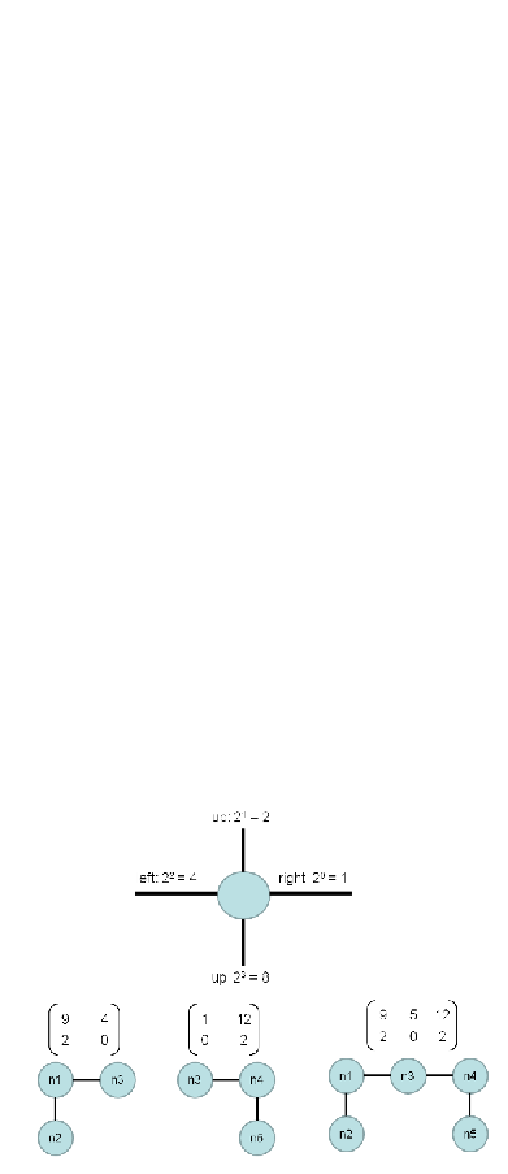
Möderl et al. (2007) have developed a MATLAB based tool named
Modular Design System
(MDS) using graph matrices. The nodal connectivity is defined by binary-coded horizontal
and vertical links as shown in Figure 4.1. Taking such coding into consideration, the set of
typical modules representing different network sections is developed and various networks
are generated by combining them in a 'LEGO building bricks fashion'. Eventually, any grid
constructed in this way has a corresponding matrix with unique elements, as shown in Figure
4.2. The result of application is the set of 2280 EPANET networks between 27 and 3977
nodes and 26 and 5704 pipes, supplied from one to six sources. The layouts have been
generated to resemble different level of complexity typical for urban or rural areas,
combining looped- and tree sections with various population densities i.e. demand
distribution. The MDS approach allows for relatively fast generation of large sample of
networks. The generated networks will be visually squared, which is more of an aesthetic
drawback; three typical layouts are shown in Figure 4.3. More importantly, the definition of
network properties is rather limited and modification of model input parameters time
consuming, especially in larger networks. Thus, the tool is still in the stage that makes it
difficult to apply for design purposes.
Figure 4.1
Binary code of nodal connections (according to Möderl et al.,2007)
Search WWH ::

Custom Search