Biomedical Engineering Reference
In-Depth Information
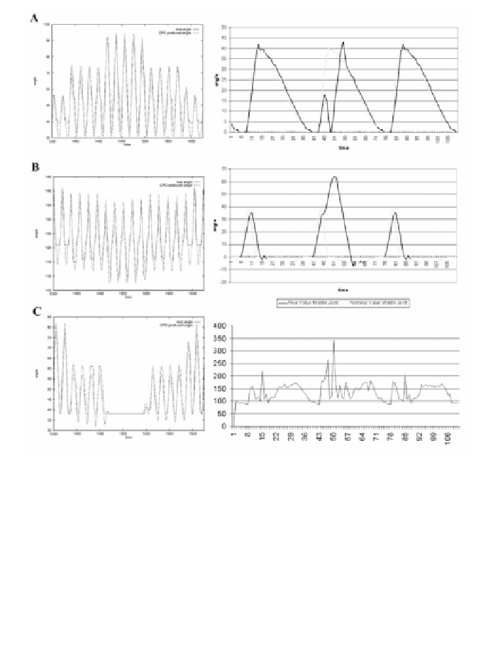
Figure 5
(left side): Traces A-C show the movements of the thoracic (
A
), basilar (
B
), and
distal (
C
) joints during transition from forward walking (pure FORWARD activation), to
diagonal walking (equal activation of FORWARD and LATERAL), to lateral walking (pure
LATERAL activation) and back. See Figure 4 for the activation pathways. (right side): A
reflex initiated in a leg during a course through a rock bed. The current in the thoracic joint
(trace C) increased as a result of the obstacle blocking the way. At the same time the angu-
lar displacement error (trace A) in the thoracic joint increased, indicating an exception in
the regular swing cycle. As a result of these factors the basilar joint controller (trace B)
initiated the reflex that elevated the leg further, thereby overcoming the obstacle.
study (see Figure 5). The data for the performance of one leg is shown in Fig-
ures 5A-C. The solid line is the real angle of the leg, measured with motor en-
coders. The angle for the distal and basilar joints increases during elevation,
while the angle for the thoracic joint increases during protraction. The frequency
was set to 1.3 Hz (19 time units on the
x
-axis). The data were taken every 1/25 s,
and the curves are directly computed from the raw data. The mean starting posi-
tion is at 37( for the thoracic joint, 121( for the basilar joint, and 30( for the