Image Processing Reference
In-Depth Information
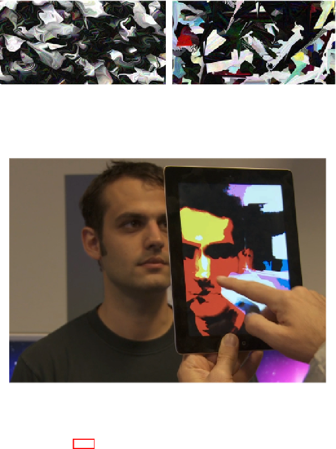
Fig. 13.6
Details of high-resolution output demonstrating “unrealistic” fluid simulation using
the
Fluid Automata
system. The left image shows the addition of a high amount of vorticity;
the right image shows the “spikiness” associated with a high amount of energy.
Fig. 13.7
Photo of iPad application using the Fluid Automata system with a live video feed
replacing the background noise texture
parameters. Figure 13.7 shows an image that is created using a live video feed as the
background image, rather than an image populated with randomly-colored pixels.
Figure 13.3 provides an overview of the fluid visualization process over the
course of a single frame. At
t
i
, the system: a) distorts the previous image texture
(if
i
0, otherwise it uses a copy of the background texture) based on user inter-
action and the current fluid profile; b) blends the background texture in with the
distorted texture based on a blending parameter (that can be updated in real-time by
a user); and then c) applies image processing filters (based on the image processing
parameters described above) to the image to create a final output texture for this
frame at
t
i
+
1
. This output texture is then used as the input texture for the next frame.
>
Search WWH ::

Custom Search