Graphics Programs Reference
In-Depth Information
usingdimensionalconstraints,itisbesttoputthedimensionsdirectlyinthe
family so that they will be visible while you are working on the family. It can
be frustrating to place a dimension only to find that one already exists in the
sketch of a solid.
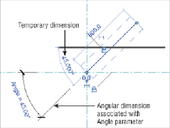
Creating angular constraints is often necessary for solid geometry. When
you need to create angular parametric behavior for a family, it is best to use
reference lines instead of reference planes. The location of the end point of
a reference line can be constrained so that the line can be rotated with the
end point serving as the axis of rotation. An angular dimension can be used
to create the parametric behavior of the reference line, as shown in
Figure
the horizontal reference plane, although it is not necessary to lock the end
point to the reference plane if the reference line is drawn connected to the
plane.
Figure 17.33
Reference line with angular parametric behavior
This type of angular constraint is useful for rotating solid geometry within
a family.
Figure 17.34
shows an extrusion that was modeled in the vertical
plane of the reference line. Because the plane of the line was used, the
extrusion is associated with the line so that, when the angle of the line
changes, the solid will stay with it. The dashed lines indicate the original
location of the line prior to changing the angle parameter to 120 degrees.