Graphics Programs Reference
In-Depth Information
Constraints and Dimensions
Making the solid geometry in your families parametric gives you the ability
to create multiple types within a single family and offers a higher level
of management and control of the properties of components. The key to
making your solid geometry parametric is to constrain the geometry to
reference planes and lines. This enables you to apply the parametric
behavior to the planes and lines, which allows for multiple solid forms
to react to changes to the parameters. Although you do have the ability
to assign parametric constraints directly to the solid geometry, it is
recommended that you assign it to reference planes or lines so that changes
to a solid that affect other solids within the family are more easily achieved
and managed.
Geometry can easily be constrained to a reference plane by using the Align
tool on the Modify tab, or you can simply drag the edge of a solid to a
reference plane or line and it will snap into alignment. Once the solid is
aligned, the padlock grip appears, allowing you to lock the alignment.
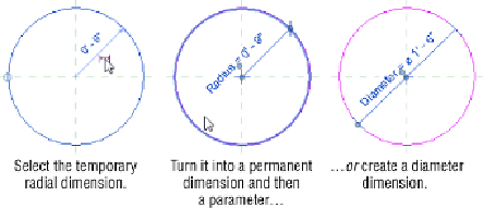
Some solid forms do not need a reference plane or line to be parametrically
managed. Whenever you are sketching a circle and want to control the
radius with a parameter, you can apply the parameter directly to the sketch.
This isdone byactivating thetemporary dimension that indicates theradius
when sketching the circle. Clicking the dimension grip will change the
temporary dimension to a permanent one, which can then be assigned to a
parameter. Alternatively, you can create a diameter dimension, as shown in
Figure 17.32
Radial and diameter dimensions
Whenyoucompleteasketchthatcontainsdimensionswithinthesketch,the
dimensions will not show unless you are in sketch mode. You can constrain
sketch lines to reference planes while working in sketch mode, but if you are