Environmental Engineering Reference
In-Depth Information
Surface elevations
EAST
1710
1710
1700
1700
1690
1690
1680
1680
1670
1670
1660
1660
160
150
140
130
120
110
0
25
50
7
100
150
200
Glacial
overburden
300
400
Weathered
to
fractured
to
sound
marine
shales
500
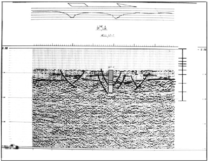
FIGURE 2.28
Seismic reflection profile for landslide study. Shown are interpreted slope failure surfaces. (Courtesy of
Woodword-Clyde Consultants.)
Velocities cannot be calculated with reliability since distances are not accurately known,
and therefore material types and stratum depths cannot be evaluated as in refraction
methods. Depths are estimated by assuming a water velocity of 2500 m/sec, but variations
in strata impedance affect the thickness scale. Test borings or refraction studies are neces-
sary for depth- and material-type determinations.
Electrical Resistivity Methods
Applications
The resistivity of soil or rock is controlled primarily by pore water conditions that vary
widely for any material. Therefore, resistivity values cannot be directly interpreted in
terms of soil type and lithology. Some applications are:
Differentiation between clean granular materials and clay layers for borrow-
material location.
●
Measurement of the thickness of organic deposits in areas difficult to access.
●
Measurement of the depth to a potential failure surface in “quick” clays in which
the salt content, and therefore the resistivity, is characteristically different near
the potential failure surface (
Section 9.5.2).
●
Location of subsurface saltwater boundaries.
●
Identification of variations in groundwater quality in homogeneous granular
deposits, as may be caused by chemical wastes leaking from a storage basin.
●
Measurement of depth to bedrock and delineation of varying rock quality.
●
Location of solution cavities in limestone and underground mines (not always
successful).
●