Environmental Engineering Reference
In-Depth Information
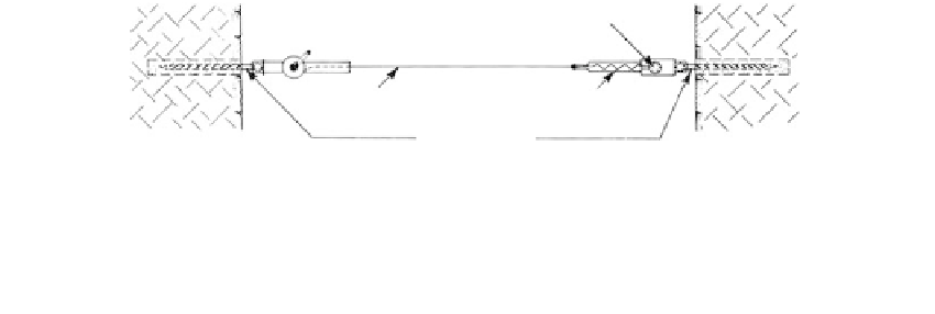
Dial gage
Invar wire
Tensioning element
Convergence
pins
FIGURE 4.7
Convergence meter. (From Silveira, J.F.A.,
Proceedings of the 1st Congress
, Brasileira de Geologia de Engenharia,
Rio de Janeiro, August, Vol. 1, 1976, pp. 131-154. With permission.)
FIGURE 4.8
Installation of convergence monuments
on a cut slope in a mine.
any potential failure surface, and extending to lower bench levels (
Figure 4.41)
.
Either pos-
itive or negative movements will be measured between any two adjacent pins.
Interpretation of where the movements are occurring along the slope requires plotting the
readings between any two pins on a section showing all the pins.
Tunnel Convergence Monitoring
There are two basic layouts for positioning the pins in the tunnel walls: one provides for
measurements across the diameter but has the often serious disadvantage of interfering
with operations, and the other provides for measurements around the perimeter with less
interference in tunneling operations.
For making measurements across the diameters of tunnels in rock, the pins are installed in
arrays positioned on the basis of the geologic structure. In
Figure 4.9,
an array for horizontally
bedded rock provides a concentration around the roof arch, since roof deflections are likely to
be the most significant movements. The base pins at points I and II are reference pins. In
Figure 4.10,
the pin array is positioned for measurements when the rock structure is dipping.
The pins are concentrated where the structure dips out of the tunnel wall, since failure is most
likely at this location. These arrays provide relatively precise measures of tunnel closure.
Stringing the wire through a series of rollers attached to pins located around the tunnel
wall, as in
Figure 4.11a,
leaves the tunnel unobstructed for construction activities.
Measurements of the net change in tunnel diameter are made but the locations of maximum