Environmental Engineering Reference
In-Depth Information
particularly along shear zones where movements are likely to be relatively large. In tunnels
they provide data based on the need for additional supports (Hartmann, 1966).
Instrument
An Invar steel wire is attached to a tensioning device and dial indicator as shown in Figure
4.6. Reference pins are grouted into tunnel walls or mounted on monuments on slopes. One
end of the wire is connected to a pin (Figure 4.6) and the instrument is attached to the oppo-
site pin
(Figure 4.7).
The wire is adjusted to a calibrated tension and the distance between
pins is measured with the dial gage. Well-made instruments, such as those of Interfels, used
properly, have an accuracy of 1
10
−5
times the measurement length (Silveira, 1976).
Slope Monitoring
As shown in
Figure 4.8,
pins are set in monuments on slope benches in a series of parallel
lines running up- and down-slope, with each line starting well behind the slope crest and
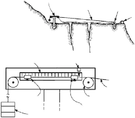
Measurement station on stable ground
Tensioned wire
Anchor on crest of slope
To alarm
Not to scale
Steel rule
Trip switch
Tensioned wire
Measurement
block
Wire guide
Trip block
Tensioning weight
FIGURE 4.5
Wire extensometer on crest of rock slope. (From FHWA, USDOT, FHA, Pub. No. FHWA-TS-89-045,
September 1989. With permission.)
FIGURE 4.6
Tensioning device and dial indicator used to measure convergence.