Environmental Engineering Reference
In-Depth Information
Triaxial Shear Strength
Apparatus and Procedures
General description is given in
Section 3.4.4
and, as applicable to rock testing, in
Section
3.5.3
and in
Table 3.28.
Strength Values
Studies have been made relating analysis of petrographic thin sections of sandstone to esti-
mates of the triaxial compressive strength (Fahy and Guccione, 1979). Relationships have
been developed for approximating peak strengths for rock masses (Hoek and Brown, 1980).
Direct Shear Strength
Purpose
The purpose is to obtain measurements of the parameters
and
c in situ
. It is particularly
useful to measure strength along joints or other weakness planes in rock masses.
φ
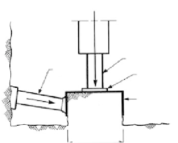
In Situ Test Procedure
A diamond saw is used to trim a rock block from the mass with dimensions 0.7 to 1.0 m
2
and 0.3 m in height, and a steel box is placed over the block and filled with grout
(Haverland and Slebir, 1972). Vertical load is imposed by a hydraulic jack, while a shear
force is imposed by another jack (Figure 3.43) until failure. All jack forces and block move-
ments are measured and recorded. Deere (1976) suggests at least five tests for each geo-
logic feature to be tested, each test being run at a different level of normal stress to allow
the construction of Mohr's envelope.
Laboratory Direct Shear Tests (See
Section 3.4.4)
If the specimen is decomposed to the extent that it may be trimmed into the direct shear
ring (
Figures 3.37c
and
3.51)
the test is performed similar to a soil test (Section 3.4.4). If pos-
sible, the shearing plane should coincide with the weakness planes of the specimen. Tests
to measure the characteristics of joints in fresh to moderately weathered rock are performed
by encapsulating the specimen in some strong material within the shear box as shown in
Figure 3.37d (ISRM, 1981). The specimen is permitted to consolidate under a normal force
and then sheared to obtain measures of peak and residual strength as described in Section
3.4.4. The normal stress is increased, consolidation permitted, and the specimen sheared
again. The process is repeated until five values of shear stress vs. normal stress is obtained,
from which a graph for peak and residual strength is constructed as shown in
Figure 3.44.
Reaction
Load jack
Steel pad
Thrust
jack
Steel frame
Rock
block
FIGURE 3.43
In situ
direct shear test.
1
−
0.7 m