Environmental Engineering Reference
In-Depth Information
To address this nonlinearity issue, multiple controllers can be optimized for different
turbine control design points. Then, as the turbine's operating point varies from one region
to another, the controllers can be switched. This usually requires a
scheduling
or
switching
parameter
, such as wind speed or pitch. Some work has been performed to study switch-
ing between controllers for wind turbines [Kraan 1992]. Often, switching between different
controllers can be problematic, in that if one simply switches between one controller and the
next, undesirable
switching transients
can occur. Kraan and Bongers [1993] describe the
use of
controller pre-conditioning
in which the next controller predicted to be activated is
prepared in advance for this task, so that switching transients are minimized.
Another modern control technique to account for changing operating points and there-
fore changing optimum gains is
adaptive control
. Bossanyi [1987] researched an adaptive
scheme that consisted of a time-varying state estimator that applied optimal control to ac-
count for varying gains. The author reported satisfactory simulation results for schemes
based on a combination of measurements of power output and shaft speed. An adaptive con-
trol method for a three-bladed turbine has been studied by Freeman and Balas [1999]. Other
more recent work in adaptive controls has been performed by Johnson [2004] and Johnson
et
al.
[2004], who reported using adaptive control to improve energy capture in Region 2. Ad-
ditional work has been done by Frost
et al
. [2008] in the use of nonlinear adaptive controls
for speed regulation in Region 3.
Tools for Control Design and Evaluation
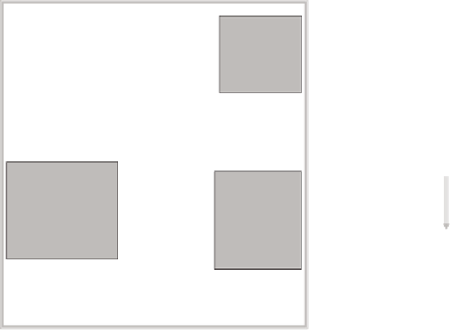
Developing advanced controls for wind turbines is a complex process, as illustrated in
Figure 14-5. This process consists of 1) determining control objectives, 2) developing simpli-
fied dynamic models from which to design the controller, 3) applying control design tools,
and 4) performing dynamic simulations to test closed-loop performance. These steps may
need to be repeated in order to design a controller with satisfactory performance in simula-
Field test
CART
CART-3
Industry
Develop
Simple
Dynamic
Models
Determine
Control
Objectives
FAST/Linear
MATLAB
Scripts
Apply
Control
Design
Tools
Simulate
Controller
Performance
FAST/
Simulink
Modify
Analyze data
Make changes
Iterate
Figure 14-5. Illustration of a typical control design, simulation, and field testing pro-
cess.
The complete process is iterative until the desired control performance is achieved.


Search WWH ::

Custom Search