Environmental Engineering Reference
In-Depth Information
Comparison of Observed and Idealized
Signal Scatter Ratios
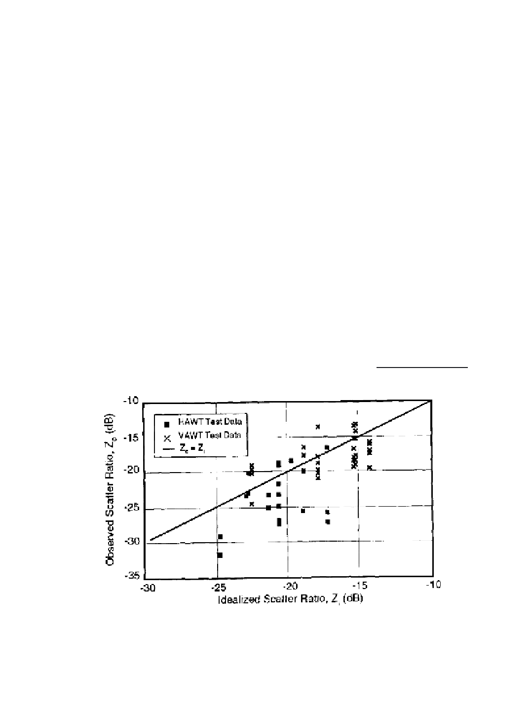
For the conditions of a given field test, Equations (9-26) can be used to calculate an
idealized scatter ratio, while the observed scatter ratio is determined for that test using
Equations (9-16). By comparing observed and idealized scatter ratios for a variety of wind
turbines and field conditions, we can estimate the
probability
that signal interference will
exceed the idealized value by a given amount. This has been done for the 75 field test
cases listed in Table 9-1 [Spera and Sengupta 1994]. Scatter ratios are compared in Figure
9-13 for the backward-scatter zone and Figure 9-14 for the forward-scatter zone.
Table 9-1. TVI Cases Analyzed for Observed
vs.
Idealized Scatter Ratios
[Spera and Sengupta 1994]
Wind
turbine
No.
of
units
Scatter
zone
No.
of
cases
Wave
lengths
(m)
WT-Receiver
distances
(m)
Data Reference
Mod-1 HAWT
"
1
"
Backward
Forward
16
5
1.6 - 5.0
1.5 - 3.7
1041 - 2745
"
[Sengupta
et al.
1981a]
"
Mod-2 HAWT
1
Backward
3
1.6 - 3.4
1603 - 6100
[Sengupta
et al.
1983a]
"
"
Forward
1
0.6
1445
"
"
2
Backward
1
3.4
6254
"
"
2,3
Forward
4
0.5 - 1.4
1354 - 1717
"
17-m VAWT
"
1
"
Backward
Forward
33
12
0.4 - 4.2
"
32 - 133 27 - 31
[Sengupta
et al.
1981b]
"
Figure 9-13. Comparison of observed and idealized signal scatter ratios for receivers
in the backward-scatter zone.
[Spera and Sengupta 1994]


Search WWH ::

Custom Search