Environmental Engineering Reference
In-Depth Information
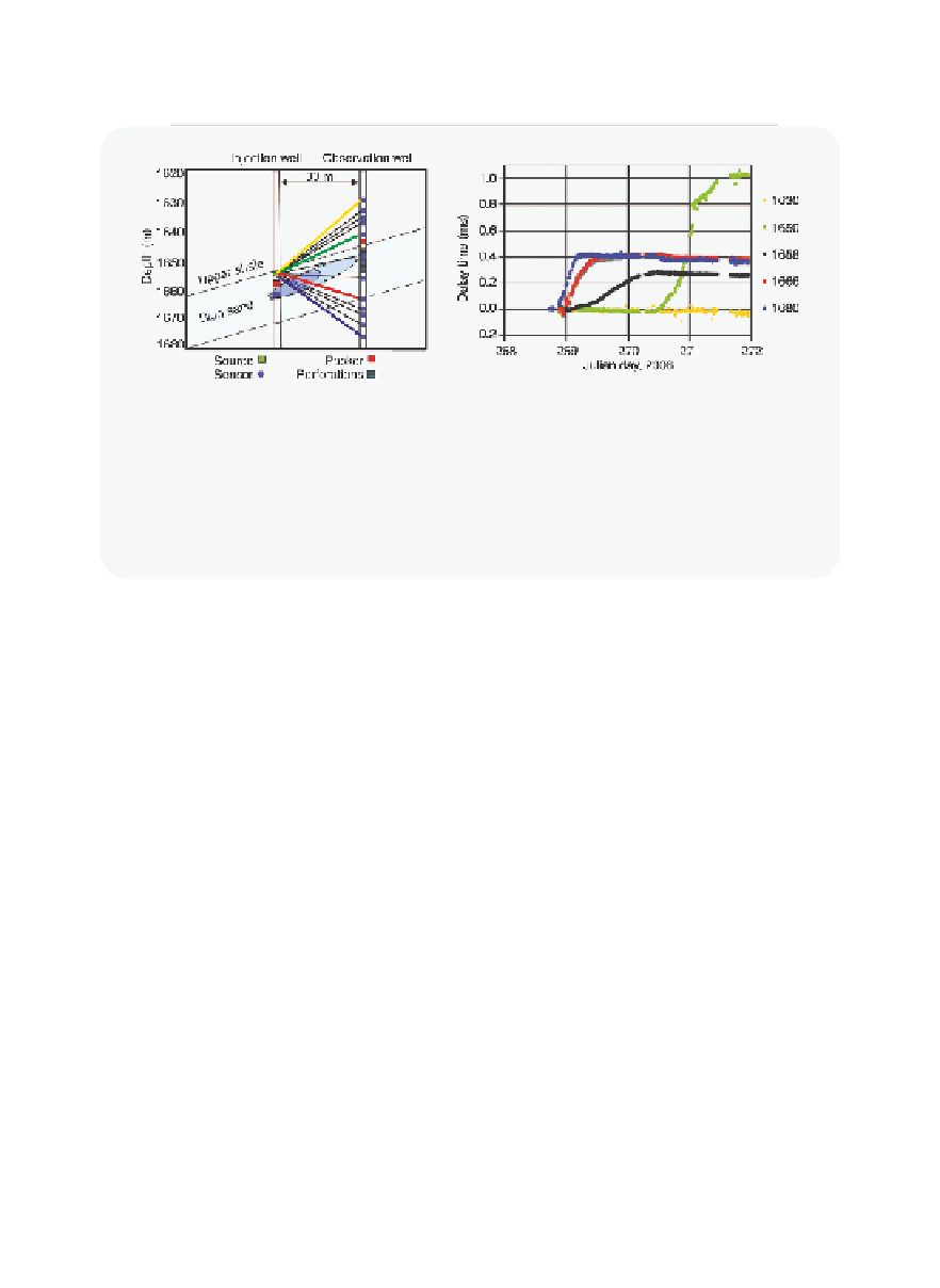
Figure 10.5.6
Seismic source approach
(Left) Sketch of ray paths from source in the injection well to receivers in the observa-
tion well. (Right) Temporal evolution of delay time for seismic energy arriving at various
receivers in the observation well. The pattern of change in delay time matches well with
a growing and spreading CO
2
plume.
Reproduced with permission from Daley et al.
[10.48]
.
other ray paths corresponding to the plume growing across the space
between the injection and observation wells.
Remote sensing (InSAR)
Another large-scale monitoring approach that has proven itself very use-
ful is InSAR (Interferometric Synthetic Aperture Radar). The concept
behind this method is depicted in
Figure 10.5.7
which shows a satellite
source and receiver and the ground surface. Briefl y, the difference in
phase between the transmitted and the received signal between subse-
quent refl ections of the same point (ideally with correction using a static
object on the ground surface known as a point scatterer) can be trans-
lated into a difference in distance which indicates defl ection of the
ground surface. This approach is used to monitor large-scale landslides
and tectonic motions with very small surface movements.
The use of InSAR for geological carbon sequestration has been dem-
onstrated as depicted in
Figure 10.5.8
for the In Salah CO
2
injection project
[10.50]. Briefl y, the In Salah project separates CO
2
from natural gas pro-
duced from several reservoirs in the area. The CO
2
is then injected into a
low-permeability sandstone using long horizontal wells. The increased
pressure in the injection formation propagates strain upward through the


Search WWH ::

Custom Search