Environmental Engineering Reference
In-Depth Information
Spin
dope and
bore fluid
delivery
Fiber
take
-up
Spinneret
Solvent exchange,
drying & module
formation
Quench bath
1
1
2
2
Typical 250µm OD hollow fiber
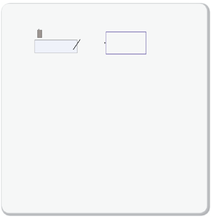
Figure 7.3.3
Hollow fi ber membranes
Schematic process to make asymmetric hollow fi bers. The starting point is homogene-
ous polymer solution (or dope) consisting of a polymer, a solvent, and additives. This
solution and the bore fl uid are fed to the spinneret. The co-extruded solution is imme-
diately immersed in a quench bath, the fi bers are collected on the take-up bobbin and
the solvent is removed. The fi bers are then assembled into modules that can contain as
much as 10
6
fi bers with an area of 10,000 m
2
/m
3
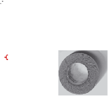
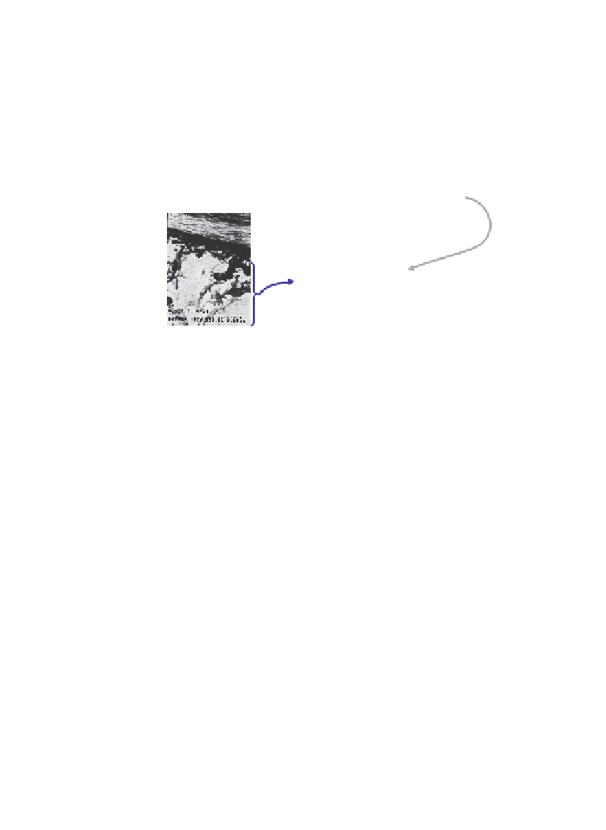
. The bottom-left fi gure shows an elec-
tron microscope picture of a detail of the hollow fi ber of the selective layer (1) and sup-
port layer (2), which can be simultaneously co-extruded to form a hollow fi ber
(bottom-right picture), which makes this process more cost-effective (i.e., about $20/m
2
,
2012 price).
Figure adapted from Koros and Lively
[7.2],
with permission from John Wiley
and Sons.
bundled into modules containing 10
6
fi bers with an area per volume ratio
of 10,000 m
2
/m
3
[7.2] (see
Figure 7.3.4
).
Given a hollow fi ber, one can use different designs for the membrane
units. These designs differ in their fl ow patterns. We saw in Section 5.2
that countercurrent fl ow gives the best separation. In our hollow fi ber
membrane unit, we can achieve a countercurrent situation as is illus-
trated in
Figure 7.3.5
.
Recently, polymer chemists have been able to synthesize hybrid
polymer-solid adsorbent materials in which these membranes contain
zeolites [7.3] or Metal Organic Frameworks [7.4].


Search WWH ::

Custom Search