Graphics Programs Reference
In-Depth Information
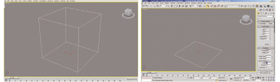
Figure 1. A polygon modeler typically starts off with a cube (depicted) or a plane
Figure 2. Moving a vertex (left), edge (middle), and face (right) to the left. The element moved is shaded
Figure 3. A vertical (left), horizontal (middle), and two diagonal cuts (right). The vertical and horizontal
cuts yield two new faces, and the diagonal cuts yield four faces where there used to be a single face
Figure 4. Examples of extruding a face. The left picture shows a cube with a cut face prior to extruding.
The middle picture shows one of the faces extruded outwards; the extruded face is shaded. The right
picture shows the same face extruded inward.


Search WWH ::

Custom Search