Graphics Reference
In-Depth Information
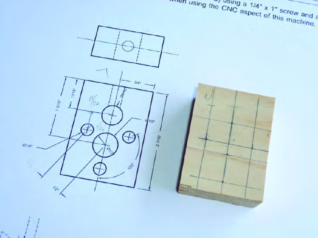
Figure 6-2. Part N marked with penciled lines to indicate drill points
Notice in Figure 6-2 how the actual Part N is identical in size to the drawing. This is a benefit to
printing out the building plans at actual size.
The three small holes you'll drill on the face of Part N have a diameter of 1/4” to match the flange
holes of the three nuts to be inserted. The hole centered between the three small holes has a diameter of
1/2” that serves as the pass-through hole for the lead screw. Finally, the mid-size hole drilled above the
1/2” hole has a diameter of 7/16” and is the hole that will intersect the 1/4” hole drilled into the edge of
Part N. This hole will carry the cross dowel (barrel nut) and the edge hole will receive the 1/4" screw to
screw into the cross dowel for mounting to the ZY Plate.
Don't forget this edge hole! In Figure 6-2 you can see that the 1/4” edge hole is drilled in such a way
that it intersects the 7/16” hole on the face of Part N. The dashed lines in the drawing represent the
depth of the 1/4” hole drilled on the edge.
After you've drilled the face holes, your piece should look like the one in Figure 6-3.
Search WWH ::

Custom Search