Graphics Reference
In-Depth Information
■
Note
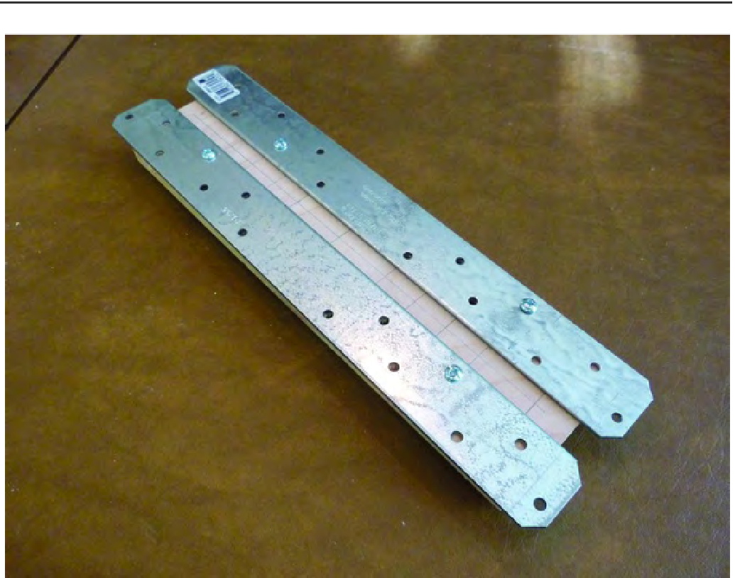
Why are you finger-tightening only two bolts on each rail? You'll be inserting Part H (with the two Strong-
Tie rails attached) into the sub-assembly you put together in Chapter 10. The rails will be inserted through the v-
groove bearings and must roll smoothly. You may have to adjust the Strong-Tie rails by pushing them outward or
inward in order to obtain a proper fit between the v-groove bearings. Finger-tightening now will allow you to more
easily adjust the rails before adding the additional 12 #8 bolts and tightening all of them down securely.
Figure 11-2. Two Strong-Tie rails attached to the Y-Axis Rail Support
Your first task will be to insert the Z-Axis Rail Support (from Chapter 10) into the ZY Plate, as shown
in Figure 11-3. Note the orientation of Part L (at top); it is pointed to the left and its counterbored hole
will be directly over the larger center hole of Part N.

Search WWH ::

Custom Search