Environmental Engineering Reference
In-Depth Information
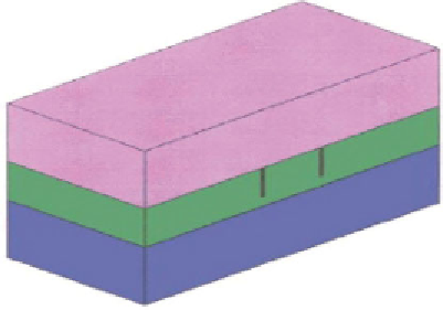
Figure 3.17
Three-layer earth DCEOR field mapping model (after Wittle and Hill, 2006b;
and Wittle et al., 2008a, & 2008c)
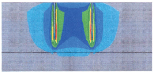
Figure 3.18
DCEOR figure 3.18 model simulation equipotential field cross-section (after
Wittle and Hill, 2006a; and Wittle et al., 2008a, 2008b, & 2008c)
densities, where
low
Joule
only
power losses are desired (i.e., high Joule
power losses are to be avoided). Figure 3.20 illustrates Joule heating (
no
conductive or convective heat transfer
) simulation results in the vicinity of
a down-hole electrode within a heavy oil reservoir. Even after 7.5 months
of DCEOR, the temperature beyond 14 ft. of the electrode surface is essen-
tially unchanged. Convective and radiative heat transfer, however, would
increase the effective heating radius.
3.9.4
Comparison of DC vs. AC Electrical Transmission
Power Loss
The power losses, as discussed above, depend only upon resistances (Equation
3.7) or resistivities (Equations 3.10 and 3.11),
for DC electrical current
.


Search WWH ::

Custom Search