Civil Engineering Reference
In-Depth Information
b
o
d
p
d
p
b
o
h
sc
h
sc
h
p
h
p
Ce
ntroidal axis of sheet
e
Ce
ntroidal axis of sheet
e
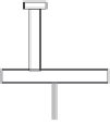
Figure 2.15 Composite beam with profiled steel decking spanning the same direction.
market that eliminated the use of traditional timber temporary forms. Ini-
tially, the new decking system served only as a replacement for the timber
formwork due to its advantages of serving as a working platform to support
the construction loads, as well as a permanent formwork for the concrete.
Once the sheets had their surfaces suitably embossed with small indentations
to ensure reliable bond with the concrete, it became an integral structural
element of the slab by providing all or a part of the main tension reinforce-
ment, and it was eventually incorporated into the overall composite floor
and framing system. Since the decking created a barrier between the con-
crete slab and the steel beam, holes were initially cut or punched into the
deck for the welding of the stud shear connectors, but it soon became pos-
sible to weld these connectors through the decking. The disadvantages of
this form of construction were the operation and cost of welding the con-
nectors through the decking on site, the limitations to maximum spans to
about 3.5 m without propping, and the addition of framing, and a “wet
trade” is involved in pouring the concrete floor that prevents a dry construc-
tion environment.
The use of composite construction can be seen now between steel beams
and different concrete slabs. As an example, the use of prestressed hollow
core concrete slabs in conjunction with steel beams to provide composite
action is a new form of construction. In this construction, the prestressed
hollow core concrete units are placed on the top of the steel beam as shown
in
Figure 2.16
. Tie steel is placed on site into the slots made at the top of the
hollow cores, which are filled with grade C25 (minimum)
in situ
concrete.
The slab rests directly on the top of the flange of the steel beam as shown in
Figure 2.16
, and shear connectors are used to ensure the composite action
between the prestressed hollow core concrete floor and the steel beam.
with hollow core concrete units. The longitudinal and transverse joints
between the hollow core concrete units are filled with
in situ
concrete so
that horizontal compressive membrane forces can be transferred through


Search WWH ::

Custom Search