Civil Engineering Reference
In-Depth Information
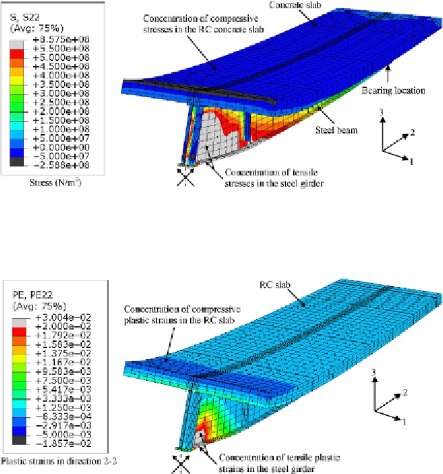
Figure 7.11 Stress (principal in direction 2-2) contours at failure of composite girder G2
(enlarged 10 times).
Figure 7.12 Plastic strain (principal in direction 2-2) contours at failure of composite
girder G2 (enlarged 10 times).
plastic strains were concentrated at midspan in the concrete (compressive
strains with negative sign) and lower steel plate girder flange (tensile strains
with positive sign). Furthermore, in
Figure 7.13
, the von Mises yield stress
contours at failure of the composite plate girder G2 are plotted. It can be seen
that the yield stresses were reached at midspan in the lower flange of the steel
plate girder. The load-midspan deflection curves predicted experimentally
and numerically were compared as shown in
Figure 7.14
.
It can be shown that
generally good agreement was achieved between experimental and numerical
Search WWH ::

Custom Search