Civil Engineering Reference
In-Depth Information
656 MPa, respectively. The web of the steel plate girders was strengthened
by stiffeners as shown in
Figure 7.8
to prevent shear failure. The concrete
slab had a width of 2184 mm and a depth of 181 mm. The composite plate
girder had an overall height of 980 mm. The measured concrete cylinder
strength of G2 was 52.5 MPa. The concrete slab had reinforcement steel
bars, as shown in
Figure 7.8
,
of Grade 60 having a yield stress of
413 MPa (60 ksi). The reinforcement bars were spaced at 209 mm longitu-
dinally and 356 mm transversely. The top and bottom reinforcement bars
had a cover of 44 mm. The shear connectors were headed studs having a
diameter of 19 mm and a height of 114 mm. Sixty pairs of headed studs were
used in the composite plate girder G2 as shown in
Figure 7.8
.
The composite
plate girders were subjected to a single concentrated load applied at midspan
via a spreader beam. The loading was applied in increments using displace-
ment control.
The composite plate girder G2 tested by Mans [
7.29
] was modeled in this
book using ABAQUS [1.29]. The finite element analysis has accounted for
the nonlinear material properties and geometry of the components as well as
the interfaces between the components. The steel-concrete composite plate
girder components were modeled using 3-D solid elements (C3D8) avail-
able in the ABAQUS [1.29] element library. Only half of the composite
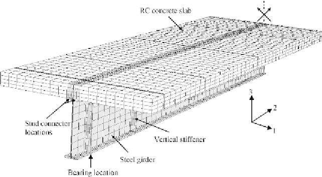
plate girder was modeled due to symmetry as shown in
Figure 7.9
. The total
number of elements used in the model shown in
Figure 7.9
was 7266. Dif-
ferent mesh sizes were tried to choose the reasonable mesh that provides
Figure 7.9 Finite element mesh of composite girder G2.
Search WWH ::

Custom Search