Civil Engineering Reference
In-Depth Information
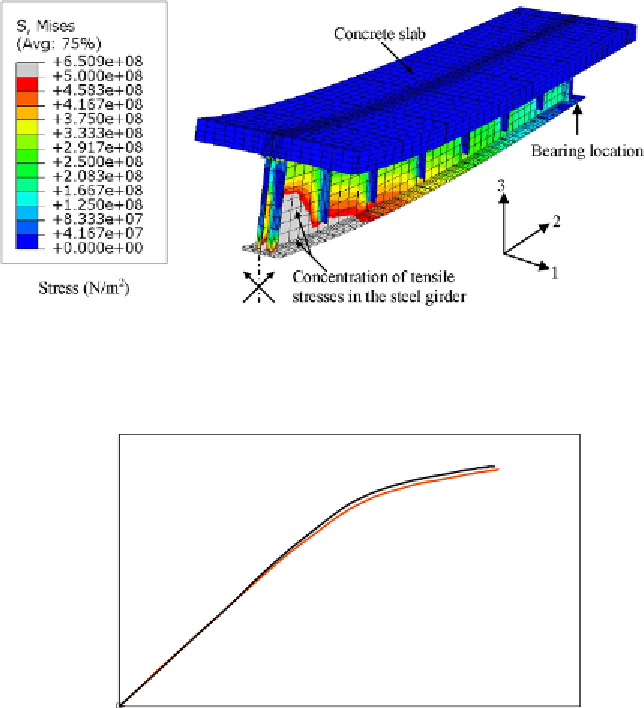
Figure 7.6 Stress (von Mises) contours at failure of composite girder G1 (enlarged 10
times).
2000
1800
1600
1400
1200
1000
800
600
400
Test
FE
200
0
0
20
40
60
80
100
120
Midspan deflection (mm)
Figure 7.7 Load-midspan deflection of composite girder G1 obtained experimentally
and numerically.
Figure 7.7
. It can be shown that generally good agreement was achieved
between experimental and numerical relationships. The ultimate failure load
the ultimate failure load predicted from the finite element analysis was
1765.5 kN at a deflection of 97.7 mm. The finite element failure load
was 1.3% higher than that observed in the test.


Search WWH ::

Custom Search