Civil Engineering Reference
In-Depth Information
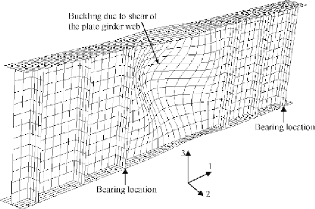
Figure 6.11 Elastic lateral buckling mode (eigenmode 1) for the small-scale built-up
I-section plate girder T2.
model initial geometric imperfections of the plate girder investigated T2.
Figure 6.11
shows the buckling mode predicted from the eigenvalue buck-
ling analysis detailed in ABAQUS [1.29]. Only the first buckling mode
(eigenmode 1) is used in the eigenvalue analysis. Since buckling modes pre-
dicted by ABAQUS eigenvalue analysis [1.29] are generalized to 1.0, the
buckling modes are factored by a magnitude of
L
u
/1000, where
L
u
is the
length between points of effective bracing. The magnitude of
L
u
/1000 is
The factored buckling mode is inserted into the load-displacement non-
linear analysis of the plate girder T2 following the eigenvalue prediction.
It should be noted that the investigation of plate girders with different slen-
derness ratios could result in different buckling modes. Hence, to ensure that
the correct buckling mode is incorporated in the nonlinear displacement
analysis, the eigenvalue buckling analysis must be performed for each plate
girder with actual geometry.
The developed finite element model for the plate girder T2 (see
Figure 6.10
) was verified against the test results detailed in [
6.27
]. The failure
loads, failure modes, and load-deflection curves obtained experimentally
Search WWH ::

Custom Search