Civil Engineering Reference
In-Depth Information
the von Mises stresses at the maximum stressed fibers at the top and bottom
flanges at midspan exceeded the measured yield stresses. In
Figure 6.5
,
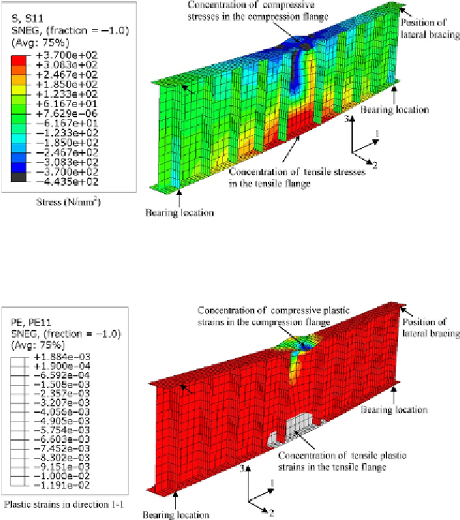
the
stress (principal stresses in direction 1-1) contours at failure of the small-scale
built-up I-section plate girder T1 are plotted. It can be seen that the yield
stresses were reached at midspan in the upper (compressive stresses with neg-
ative sign) and lower flanges (tensile stresses with positive sign). In addition,
in
Figure 6.6
,
the plastic strain (principal strains in direction 1-1) contours at
failure of the small-scale built-up I-section plate girder T1 are plotted. It can
Figure 6.5 Stress (principal in direction 1-1) contours at failure of the small-scale built-
up I-section plate girder T1 (enlarged 5).
Figure 6.6 Plastic strain (principal in direction 1-1) contours at failure of the small-scale
built-up I-section plate girder T1 (enlarged 5).
Search WWH ::

Custom Search