Civil Engineering Reference
In-Depth Information
Surface 2
Steel beam
Concrete
Surface 3
Headed stud
Z
Y
Profiled sheeting
X
Surface 1
Reinforcement bar
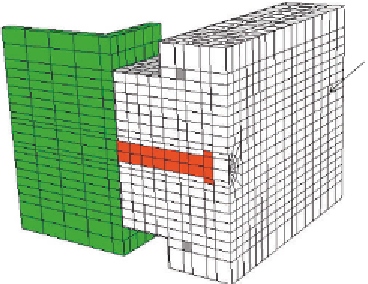
Figure 5.32 Finite element mesh of Model (A) as detailed by Ellobody and Young [2.71].
Steel beam
Profiled steel sheeting
Surface 2
Concrete
Headed stud
Surface 3
Y
Z
Reinforcement bar
X
Surface 1
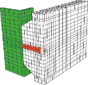
Figure 5.33 Finite element mesh of Model (B) as detailed by Ellobody and Young [2.71].
of the head of the stud is taken 1.5
the stud diameter, and its thickness is
0.5
the diameter. The circular cross-sectional area of the reinforcement
bar was simulated by the equivalent rectangular cross-sectional area in the
finite element modeling. It is assumed that the effect of separation of the pro-
filed steel sheeting from the concrete slab at certain load level has little effect
on the concrete slab. Hence, the nodes of the concrete elements are attached
to the nodes of the profiled steel sheeting elements. Jayas and Hosain [2.47]
observed that the separation of the concrete behind the shear connector


Search WWH ::

Custom Search