Civil Engineering Reference
In-Depth Information
Plane-stress and plane-strain structures can be modeled using 2D solid
elements. The naming conventions for the elements depend on the element
type (PE or PS) for (plane strain or plane stress), respectively, and number of
nodes in the element. For example, CPE3 elements are continuum (C),
plane-strain (PE) linear elements having three (3) nodes, as shown in
Fig-
ure 5.3
. The elements have 2 active degrees of freedom per node in the ele-
ment plane. Quadratic 2D elements are suitable for curved geometry of
structures. Structural metallic link members and metallic truss members
can be modeled using 1D solid elements. The naming conventions for
1D solid elements depend on the number of nodes in the element. For
example, C1D3 elements are continuum (C) elements having three (3)
nodes. The elements have 1 active degree of freedom per node.
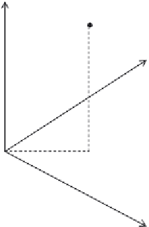
Axisymmetric solid elements are 3D elements that are used to model
metal structures that have axisymmetric geometry. The element nodes are
commonly using cylindrical coordinates (
r
,
y
,
z
), where
r
is the radius from
origin (coordinate 1),
y
is the angle in degrees measured from horizontal axis
(coordinate 2), and
z
is the perpendicular dimension (coordinate 3) as shown
in
Figure 5.4
. Coordinate 1 must be greater than or equal to zero. Degree of
freedom 1 is the translational displacement along the radius (
u
r
) and degree of
freedom 2 is the translational displacement along the perpendicular direction
(
u
z
). The naming conventions for axisymmetric solid elements with non-
linear asymmetric deformation depend on the number of nodes in the ele-
ment and integration type. For example, CAXA8R elements are continuum
(C) elements and axisymmetric solid elements with nonlinear asymmetric
Z
(
r
,
q
,
z
)
Y
z
r
q
Angle in degrees
X
Figure 5.4 Cylindrical coordinates for axisymmetric solid elements.


Search WWH ::

Custom Search