Civil Engineering Reference
In-Depth Information
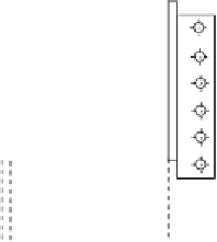
4.6.3.23 Design of Cross Girder-Main Truss Connection
The cross girder is designed as a simply supported beam on main trusses;
therefore, once again, the connection is mainly transferring shear forces
(maximum reaction from cross girders of 1600.8 kN) (see
Figure 4.205
).
We can determine the required number of bolts as follows:
1164
1
206
¼
5
:
N
3
¼
:
6 taken as 6 bolts,
:
1164
1
103
¼
11
N
2
¼
:
3 taken as 12 bolts
4.6.3.24 Design of Wind Bracings
Wind forces acting on the investigated deck highway bridge (see
Figure 4.206
)
as well as any other lateral forces directly applied to the bridge are transmitted
to the bearings by systems of upper and lower wind bracings as well as cross
bracings. The upper and lower wind bracings carry wind forces on the main
truss as shown in
Figure 4.206
.
Wind bracings are quite important to the lat-
eral stability of the upper chord compression members since they define the
buckling outside the plane of the truss, and therefore, wind forces applied to
this bridge can be sufficiently estimated using the design rules specified in EC1
[3.2] as follows:
1
2
rv
b
CA
ref
,
x
v
b
¼ c
dir
c
season
v
b
,
0
¼
1
F
w
¼
:
0
1
:
0
26
¼
26m
=
s
Q
D+L+
f
= 1164.1 kN
N
3
N
4
Figure 4.205 The connection between a cross girder and the main truss.


Search WWH ::

Custom Search