Civil Engineering Reference
In-Depth Information
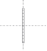
26 cm
y
1.6
x
x
1.4
1.6
y
Figure 4.201 The cross section of the diagonal tension member D
3
.
The bolts used in connecting the member with gusset plates are M27
high-strength pretensioned bolts having a clearance of 3 mm (hole diameter
¼
30 mm):
12 cm
2
A¼
2
26
1
:
6+32
:
8
1
:
4
¼
129
:
92 cm
2
A
net
¼
129
:
12
4
3
:
0
1
:
6
¼
109
:
Af
y
g
M0
¼
129
:
12
275
100
1
N
pl
,
Rd
¼
¼
3,550,800N
¼
3550
:
8kN
>
N
Ed
:
0
¼
3284
:
3kN
0
:
9
A
net
f
u
g
M2
¼
0
:
9
10,992
430
1
N
u
,
Rd
¼
¼
3,403,123N
¼
3403
:
1kN
:
25
>
N
Ed
¼
3284
:
3kN
4.6.3.20 Design of the Compression Diagonal Member D
2
compressive design force of
4706.6 kN can be designed as follows. To
classify the cross section chosen (see
Figure 4.202
)
,
s
235
f
y
r
235
275
e ¼
¼
¼
0
:
924
C
1
¼
180mm,
t
fl
¼
30,
C
1
=
t
fl
¼
180
=
30
¼
6
:
0
<
30
:
5 Flange is Class 1
ð
Þ
C
2
¼
300mm,
t
w
¼
20,
C
2
=
t
fl
¼
300
=
20
¼
15
<
30
:
5 Web is Class 1
ð
Þ
A¼
2
26
3+30
2
2
¼
276 cm
2


Search WWH ::

Custom Search