Civil Engineering Reference
In-Depth Information
d
1
= 26 cm
y
1
C
1
= 12.7
x
x
C
2
= 32.4
1
1
y
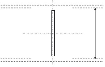
Figure 4.199 The cross section of the vertical members V
3
and V
5
.
26 cm
y
3.4
x
x
2.4
3.4
y
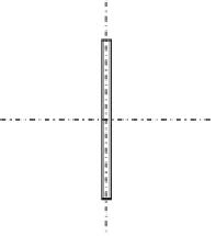
Figure 4.200 The cross section of the diagonal tension member D
1
.
connecting the member with gusset plates are M27 high-strength preten-
sioned bolts having a clearance of 3 mm (hole diameter
¼
30 mm). The
member can be designed as follows:
08 cm
2
A
net
¼
246
:
88
4
3
:
4
3
¼
206
:
Af
y
g
M0
¼
246
:
88
275
100
1
N
pl
,
Rd
¼
¼
6,789,200N
¼
6789
:
2kN
>
N
Ed
:
0
¼
6203
:
9kN
0
:
9
A
net
f
u
0
:
9
20,608
430
1
N
u
,
Rd
¼
g
M2
¼
¼
6,380,236
:
8N
¼
6380
:
2kN
:
25
>
N
Ed
¼
6203
:
9kN
4.6.3.19 Design of the Diagonal Tension Member D
3
sile design force of 3284.3 kN can be designed adopting the same procedures
used with D
1
as follows:


Search WWH ::

Custom Search