Civil Engineering Reference
In-Depth Information
We can now calculate the design plastic moment resistance as follows:
M
pl
,
Rd
¼
14,168
:
4
343
:
1 + 3173
:
7
118
:
1 + 3484
:
3
18
:
1
=
2
+ 3830
:
8
19
:
9
=
2 + 7585
:
6
881
:
9 + 9405
1762
:
9
¼
28,575,456
:
5kNmm
¼
28,575
:
>
:
5kNmm
26,223
26 kNm
ð
Then O
:
K
:
Þ:
Design of the Intermediate Composite Plate Girder Cross Section
at Quarter-Span
Since it is decided to reduce the cross section at quarter-span, as shown in
Figure 4.106
, we should check the safety of the proposed cross section
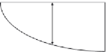
against different stresses. Assuming the bending moment diagram is a
second-degree parabola (see
Figure 4.114
), we can determine the bending
moment at quarter-span as follows:
D
26,223
2
;
1
2
26
¼
then
D¼
6555
:
8kNm
:
The design moment at quarter-span (
M
Ed
)
¼
26,223.26
6555.8
¼
19,667.5 kNm. We can now repeat the previous procedures adopted for the
heavier cross section for the design of the smaller steel plate girder cross
section shown in
Figure 4.115
:
14,168
:
4 + 3173
:
7+
x
500
275
=
1000
¼
5775 + 7656 + 500
30
x
ð
Þ
275
=
1000
17,342
:
1 + 137
:
5
x ¼
13,431
137
:
5
x
+ 4125
2
137
:
5
x ¼
213
:
9
Then,
x¼
0.78 mm.
The design plastic moment resistance can be calculated as follows:
M
pl
,
Rd
¼
14,168
:
4
325
:
78 + 3173
:
7
100
:
78 + 107
:
3
0
:
78
=
2
:
8
29
:
=
2 + 7656
899
:
22 + 5775
1784
:
+ 4017
22
22
¼
22,182,667
:
7kNmm
¼
22 182
:
7kNmm
>
19,667
:
5kNm
ð
Then O
:
K
:
Þ:
M
2
kN m
26,223.26 kN m
D
12 m
12 m
24 m
Figure 4.114 Calculation of bending moment acting at quarter span.


Search WWH ::

Custom Search