Civil Engineering Reference
In-Depth Information
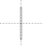
35 cm
y
1.4
x
x
1
y
Figure 4.77 The cross section of the diagonal tension members D
5
and D
4
.
4.3.3.22 Design of the Diagonal Member D
5
a maximum tensile design force of 1668.5 kN and a minimum compression
force of
526.5 kN. We can use the same cross section used for V
5
and
check the safety of the member against the tensile and compressive forces
as follows.
Design as a Tension Member
The bolts used in connecting the member with gusset plates are M27 high-
strength pretensioned bolts having a clearance of 3 mm (hole diameter
Ø
¼
30 mm):
2cm
2
A¼
35
1
:
4
2+37
:
2
1
¼
135
:
4cm
2
A
net
¼
135
:
2
4
3
:
0
1
:
4
¼
118
:
Af
y
g
M0
¼
135
:
2
275
100
1
N
pl
,
Rd
¼
¼
3,718,000N
¼
3718
:
0kN
>
N
Ed
:
0
¼
1668
:
5kN
0
:
9
A
net
f
u
g
M2
¼
0
:
9
11,840
430
1
N
u
,
Rd
¼
¼
3,665,664N
¼
3665
:
7kN
:
25
>
N
Ed
¼
1668
:
5kN
Design as a Compression Member
l
b
x
¼
9600mm
l
b
y
¼
8640mm


Search WWH ::

Custom Search