Civil Engineering Reference
In-Depth Information
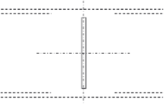
4.3.3.19 Design of the Compression Vertical Member V
3
compressive design force of
3190.7 kN can be designed as follows. To
classify the cross section chosen (see
Figure 4.73
),
s
235
f
y
r
235
275
e ¼
¼
¼
0
:
924
C
1
¼
336mm,
t
fl
¼
16,
C
1
=
t
fl
¼
336
=
16
¼
21
:
<
:
ð
Þ
0
30
5 Flange is Class 1
C
2
¼
159mm,
t
w
¼
24,
C
2
=
t
fl
¼
159
=
24
¼
6
:
6
<
30
:
5 Web is class 1
ð
Þ
32 cm
2
A¼
2
35
2
:
:
2
1
:
6
¼
224
:
4+35
2
3
4
3
8
2
I
x
¼
1
:
6
35
:
=
12 + 2
35
2
:
=
12 + 35
2
:
4
18
:
8cm
4
¼
65,273
:
6
3
4
35
3
12
¼
17,162 cm
4
I
y
¼
35
:
2
1
:
=
12 + 2
2
:
=
r
I
x
A
r
65,273
:
8
i
x
¼
¼
¼
17
:
06 cm
224
:
32
r
I
y
A
r
17162
224
i
y
¼
¼
¼
8
:
75 cm
:
32
l
b
y
¼
6750mm
l
b
x
¼
7500mm
L
cr
i
1
l
1
l¼
d
1
= 35 cm
y
2.4
C
1
= 15.9
x
x
C
2
= 33.6
2.4
1.6
y
Figure 4.73 The cross section of the vertical compression member V
3
.


Search WWH ::

Custom Search