Civil Engineering Reference
In-Depth Information
a
A
b
60 m
R
A
g
vk
= 78.1 kN/m
375 kN
375 kN
q
vk
= 43.8 kN/m
1.2 m
1.0
0.98
+
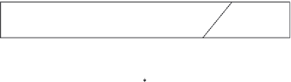
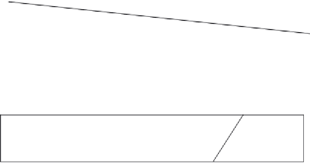
Figure 4.65 Determination of the reaction R
A
using the influence line method.
J
1
J
2
J
3
J
4
J
5
J
6
-4191.2
-7449.1
-9773.9
-11165.7
-11624.1
6711.5
5372.3
4086.1
2850.8
1668.5
-
4
195.1
-
2
226.1
-
1
302.9
-3190.7
J
13
J
7
J
9
J
8
4191.2
7449.1
J
10
9773.9
J
11
11165.7
J
12
5822.2 kN
Figure 4.66 Distribution of forces in the N-shaped main truss under the dead and live
cases of loading.
carrying a compressive design force of
11,624.1 kN. It should be noted
that box sections used with truss bridges may be bolted or welded. In bolted
box sections, channels are commonly used in webs and connected to cover
flange plates using bolts. However, bolted box sections require a lot of
detailing and are time-consuming to fabricate. That is why welded box sec-
tions consisting of flange and web plates have been commonly used in brid-
ges in the last decades, particularly for continuous chord members owing to
the advanced techniques available nowadays for butt welding, while verticals
and diagonals of truss bridges can be designed as bolted members since they
are not continuous and can be assembled and erected in the construction
field to avoid transportation problems. To assume a reasonable cross section


Search WWH ::

Custom Search