Civil Engineering Reference
In-Depth Information
It should be noted that, from the equilibrium of the truss (see
of the calculated lower chord member L
2
but with a negative sign (a com-
pression force of 4191.2 kN). It should also be noted that the force in the
lower chord member L
1
is zero under vertical loading.
4.3.3.7 Calculation of Force in the Diagonal Chord Member D
5
To determine the force in the diagonal chord truss member D
5
(see
Figure 4.60
)
using the influence line method, we can follow the simple pro-
cedures of putting a unit concentrated moving load at point a adjacent to
for the other side of section
s
-
s
to calculate the force in the member. Then,
we put the unit concentrated moving load at point b adjacent to section
s
-
s
,
shown in
Figure 4.60
, and study the equilibrium of the truss for the other
side of section
s
-
s
to calculate the force in the member. The influence line
of the diagonal member consists of two triangles as shown in
Figure 4.60
having different signs. After that, we can put the previously calculated dead
and live loads acting on a main truss in the longitudinal direction. It should
be noted that the live loads can be put on the negative or positive triangle to
s
a
D
5
V
6
V
5
7.5
F
sin
α
B
b
A
s
6 m
24 m
30 m
g
vk
= 78.1 kN/m
375 kN
375 kN
q
vk
= 43.8 kN/m
1.2 m
375 kN
375 kN
q
vk
= 43.8 kN/m
1.2 m
1.281
0.512
0.486
-
+
0.615
0.641
1.281
2.66 m
4.34 m
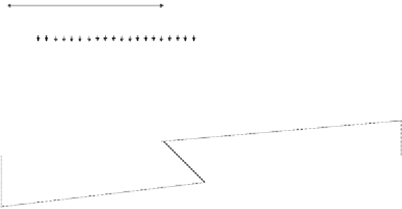
Figure 4.60 Determination of the force in diagonal member D
5
using the influence line
method.


Search WWH ::

Custom Search