Civil Engineering Reference
In-Depth Information
compression or tension should be derived from the bilinear diagram given
struction (e.g., propped or unpropped). For class 1 and 2 composite cross
sections with the concrete flange in compression, the nonlinear resistance
to bending
M
Rd
may be determined as a function of the compressive force
in the concrete
N
c
using the following simplified expressions, as shown in
N
c
N
c
,
el
M
Rd
¼M
a
,
Ed
+
M
el
,
Rd
M
a
,
Ed
for
N
c
N
c
,
el
ð
3
:
72
Þ
N
c
N
c
,
el
N
c
,
f
N
c
,
el
M
Rd
¼M
el
,
Rd
+
M
pl
,
Rd
M
el
,
Rd
for
N
c
,
el
N
c
N
c
,
f
ð
3
:
73
Þ
74
Þ
where
M
a,Ed
is the design bending moment applied to structural steel section
before composite behavior,
M
c,Ed
is the part of the design bending moment
acting on the composite section, and
k
is the lowest factor such that a stress
limit is reached, where unpropped construction is used, the sequence of
construction should be taken into account, and
N
c,el
is the compressive force
in the concrete flange corresponding to moment
M
el,Rd
.
M
el
,
Rd
¼M
a
,
Ed
+
kM
c
,
Ed
ð
3
:
M
,
M
,
Rd
Rd
1
2
M
M
pl
Rd
pl
Rd
1.0
1.0
M
M
el
,
Rd
el
,
Rd
M
M
pl
,
Rd
pl
,
Rd
M
a
,
Ed
M
pl
,
Rd
N
,
N
,
c
c
N
N
N
,
N
,
1.0
1.0
c
,
el
c
f
c
N
,
el
c
f
N
c
f
c
f
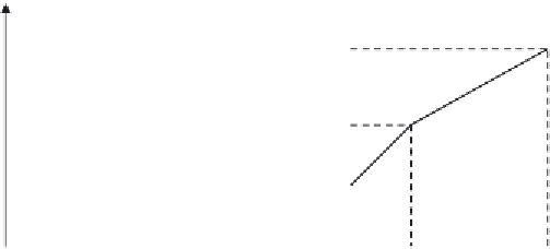
Key:
1 Propped construction
2 Unpropped construction
Figure 3.30 Simplified relationship between M
Rd
and N
c
for sections with the concrete


Search WWH ::

Custom Search