Civil Engineering Reference
In-Depth Information
up to 3-7 m. LM3 contains a set of assemblies of axle loads representing spe-
cial vehicles (e.g., for industrial transport), which can travel on routes per-
mitted for abnormal loads. It is intended for general and local verifications.
Finally, LM4 contains a crowd loading, intended only for general verifica-
tions. This crowd loading is particularly relevant for bridges located in or
near towns if its effects are not covered by Load Model 1. Load Models
1, 2, and 3, where relevant, should be taken into account for any type of
design situation (e.g., for transient situations during repair works). Load
Model 4 should be used only for some transient design situations. Load
Model 1 consists of the following two partial systems: double-axle concen-
trated loads (tandem system, TS) and uniformly distributed loads (UDL sys-
tem). For double-axle concentrated loads, each axle has a weight of
a
Q
Q
k
where
a
Q
are adjustment factors. No more than one tandem system should
be taken into account per notional lane and only complete tandem systems
should be taken into account. For the assessment of general effects, each tan-
dem system should be assumed to travel centrally along the axes of notional
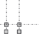
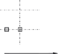
lanes. Each axle of the tandem system should be taken into account with two
identical wheels, the load per wheel being therefore equal to 0.5
a
Q
Q
k
. The
contact surface of each wheel should be taken into account as a square of side
0.40 m (see
Figure 3.7
)
. On the other hand, uniformly distributed loads have
a weight of
a
q
q
k
per square meter of notional lane, where
a
q
are adjustment
2.0
≥0.5
2.0
1.2
x
0.4
0.4
Figure 3.7 Application of tandem systems for local verifications according to EC1 [
3.1
].


Search WWH ::

Custom Search