Civil Engineering Reference
In-Depth Information
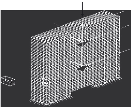
Load
Steel beam
Shear connector
Concrete slab
Area 1
Area 2
Aspect ratio
(
x
:
y
:
z
) = (1:1:1.6)
Y
Detail A
X2
X
Z
Recess
X1
Figure 2.24 Finite element representation of push-off test specimen modeled by Kalfas
et al. [
2.67
].
investigate the initial stress distribution of the shear stud connector in the
push-off test under consideration. The distributions of flexural and shear
stresses along the stud shank were given. The stresses were concentrated
around the root of the stud shank below a height of 20 mm. The authors
found that the flexural deformation of the stud shear connector was greater
than that in the case of cast in place slabs, which can resist the splitting force
better through adequate reinforcement. The study was based on linear elastic
material properties to investigate initial stresses only. The load-slip curves of
the stud, shear stud capacity, and modes of failure were not obtained from
this finite element study.
nonlinear finite element model to investigate the behavior of headed shear
stud connector in solid slabs. The results obtained from the finite element
analysis compared well with the experimental results conducted by Ellobody
the load-slip behavior of the headed studs, and the failure modes were accu-
rately predicted by the finite element model. A parametric study was con-
ducted to investigate the effects of the change in headed stud diameter and
height and concrete slab strength. The results of the finite element model
were compared with the American, British, and European specifications
for steel-concrete composite structures. It was concluded that the European
code provides good agreement with experimental and finite element results,


Search WWH ::

Custom Search