Environmental Engineering Reference
In-Depth Information
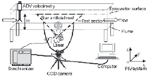
Fig. 3. Schematic diagram of the experimental apparatus and the PIV system
The basic optical devices of the PIV system were designed according to the experimental
configuration specified by TSI Inc (USA). The light sheets were generated by an Nd: YAG
laser capable of producing 3-5 ns, 120 mJ pulses at a repetition frequency of 15 Hz. The
digital images were captured using a high-resolution CCD camera with two million pixels.
The maximum frame rate of the camera was 32 f/s. A CCD camera (Power View 4MP)
coupled to PC image acquisition software was used to acquire images. The operation of the
laser and the camera was synchronized by a digital delay pulse generator. Selecting
reflective polyvinyl chloride powder with a mean diameter of 10
μ
m and density of 1050
kg/m
3
was added to the water as a trace particle.
4. Flow field characteristics of a single hollow cube artificial reef
It is known that the structure of flow field within and around artificial reefs plays an
important role in their ecological effects. The flow field effect is one of the most important
ecological effects, therefore making artificial reefs with configurations specifically designed
to induce suitable flow field structures has been of great interest to marine ecologists and
engineers in recent decades. The upwelling and back vortex flow is the major flow field
character, which is an important hydrodynamic characteristic of artificial reefs. Some
nomenclatures are listed for analyzing and discussing these flow field characteristics
qualitatively and quantitatively. The upwelling field is defined where the flow velocity of
Nomenclature
U
in
: inlet current velocity (cm/s)
h
: the height of artificial reef model (cm)
H
: the depth of water (cm)
r: the ratio of reef height to water-depth
H
up
: the height of upwelling field (cm)
S
up
: the area of upwelling field (cm
2
)
S
e
: the area of back vortex flow (cm
2
)
L
e
: the length of back vortex flow (cm)
V
max
: the maximum upwelling current
velocity (cm/s)
V
a
: the average upwelling current velocity
(cm/s)
S
: the incident flow area of artificial reef
model (cm
2
)
S
upA
: unit reef effect for the area of
upwelling
S
eA
: unit reef effect for the area of back
vortex flow field
H
upA
: unit reef effect for the height of
upwelling field
L
eA
: unit reef effect for the length of back
vortex flow field
L
rp
: the length of water current reattachment
point from the end of reef model (cm)


Search WWH ::

Custom Search