Environmental Engineering Reference
In-Depth Information
SIMPLEC algorithm was employed for pressure-velocity coupling. High-resolution
discretization schemes were used for the discretization of mass and momentum equations.
The equations were linearized using an implicit solution and iterated to achieve a converged
solution. Convergence was assumed for each time step when all residuals fall below 10
−3
,
and a maximum of 100 iterations per time step was considered if the residuals failed to pass
these thresholds.
3. Experimental methods
In recent decades, PIV has become a powerful technique for measuring instantaneous
velocity fields. Highly reflective particles are thrown into the flume, and a light sheet
produced by a laser is projected into the flow field of interest. Then, the light reflected by
these particles is captured by a high-speed camera. The calculation of the speed of the
particles in the raw particle images is based on the cross-correlation, and techniques such as
the erroneous vector correction are also employed to reduce the computing error. The PIV
systems are described in detail below.
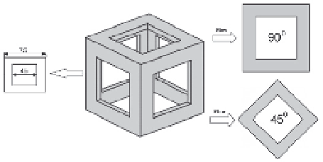
The structure and arrangement of a single hollow cube artificial reef model are shown in
Fig. 2. In this study, the reef block model was scaled by a factor of 1:20 to satisfy the physical
constraints of the flume measuring area and avoid inducing an undesirable channel wall
effect. The hollow cube artificial reef model was composed of five Plexiglas faces, with a
width of 7.5 cm and 4.5 cm square openings. The artificial reef model was arranged at 90
0
and 45
0
angles at the bottom of the flume. All of the test sections are based on the axial plane
of the artificial reefs.
Fig. 2. Structure and arrangements of a single hollow cube artificial reef model
As shown in Fig. 3, a three-dimensional coordinate system (x-y-z) was set up to build the
PIV experiment with the origin at the center of the artificial reef. The internal dimensions of
the flume were 22.00×0.45×0.60 m (length ×width ×height), and the water depth of test (
H
)
was 0.4 m. The maximum test section was 45 cm wide, 60 cm deep and 100 cm long. The
sides and bottom of the test area in the center of the water channel were composed of glass
to facilitate PIV measurement of the flow fields at various positions around the artificial reef
model. A centrifugal pump was fixed on the left of the flume and affords flow velocities of
U
1
=6.7, U
2
=11.0 and U
3
=18.0 cm/s. The experimental flow velocities were chosen according
to the characteristic flow rate of the practical sea area, and the corresponding physical
values were 0.3 m/s, 0.5 m/s and 0.8 m/s. The inlet flow velocity was measured using
acoustic Doppler current velocimetry.

Search WWH ::

Custom Search