Environmental Engineering Reference
In-Depth Information
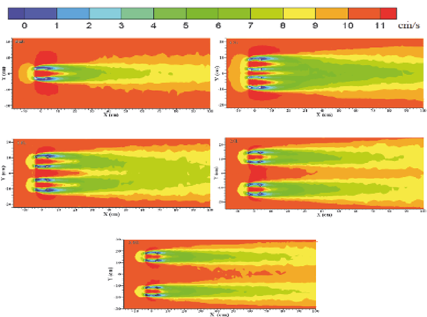
Fig. 18. Horizontal flow velocity contour plots of a single and two parallel artificial reefs
with different spacings (the horizontal cross-section is z=1/2
h
,
h
=7.5 cm)
The mutual effect of two reefs is very strong, and the slow flow velocity fields in the front
and the back of two artificial reefs nearly connect when the spacing is 0.5
h
. Thus, a larger
area of slow velocity flow field is produced for a 0.5
h
gap distance. When the spacing
increases to 1.0
h
, downstream of the reefs, the flow speed begins to increase, and the
construction of the flow field presents a trend of separation. The slow velocity flow fields
behind two artificial reefs are separated from each other by and large when the spacing is
2.0
h
. After that point, the structure of the flow field for each artificial reef becomes the same
as the single condition, and the interaction between the two reefs is slight when the distance
increases to 3.0
h
.
5.2 Two vertical hollow cube artificial reefs
Fig. 19 compares the upwelling field of two vertical artificial reefs with different spacings.
As shown in the graphs, for different spacings, the latter artificial reef causes little impact on
the upwelling field of the first artificial reef. With different spacings, the scales of the
upwelling field of the first reef are the same as that of a single reef. Nevertheless, with the
increase of the vertical spacing from 2.0
h
to 12.0
h
, the height of the upwelling field of the
second incident flow artificial reef increases gradually. When the spacing is 12.0
h
, the height
of the upwelling field of two artificial reefs is close, but the area gap is greater.

Search WWH ::

Custom Search