Information Technology Reference
In-Depth Information
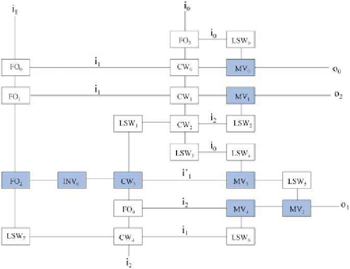
Fig. 25.
QCA layout of Mx-cqca gate testable with only all 0s and all 1s test vectors
for any single missing/additional cell defect (the shaded devices represent their fault
tolerant counterpart)
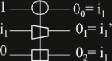
Fig. 26.
MX-cqca gate for fanout and inversion of input B
- Step 2: The three variable functions generated at every node in Step 1 are
mapped to their MX-cqca based implementation based on the thirteen stan-
dard functions. The MX-cqca based implementation of thirteen standard func-
tions is shown in Table
6
.
- Step 3: The nodes which have fanout of more than one are identified, and
MX-cqca gates are used to form the copy of the signals which have fanout of
more than one.
Search WWH ::

Custom Search