Information Technology Reference
In-Depth Information
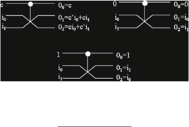
(a) Fredkin gate
(b) Fredkin gate when C=0
(c) Fredkin gate when C=1
Fig. 1.
Fredkin gate and its working mode
Table 1.
Truth table for Fredkin gate
c
i
0
i
1
o
0
o
1
o
2
000000
001001
010010
011011
100100
101110
110101
111111
distribution along diagonal axes and is given by Eq.
1
(here Pi denotes the elec-
tronic charge at dot i). When electrons are in dots 1 and 3, P =
−
1 (Logic '0')
and when electrons in dots 2 and 4, P = +1 (Logic '1') [
70
]. Figure
2
(a) and (b)
illustrate the 4 quantum dots in a QCA cell, and the implementation of logic '0'
and logic '1' in a QCA cell, respectively.
=
(
P
2+
P
4)
−
(
P
1+
P
3)
P
(1)
P
P
P
P
1+
2+
3+
4
The basic QCA device is the majority voter (MV) or majority gate, which
is represented as Y =
X
1
X
2
+
X
2
X
3
+
X
1
X
3
, where Y is the majority of the
inputs
X
3
. Figure
3
(a) shows the majority voter. The majority voter
can be made to work as an AND gate or as an OR gate, by setting one of the
inputs as '0' and '1', respectively (For example, if
X
1
,
X
2
and
X
3
= 0 we will get Y =
X
1
X
2
.
Similarly if
X
2
). Another important gate in
QCA is the inverter, which is formed when a QCA cell, say cell-1 is placed 45
ⓦ
to another QCA cell, for example cell-0, cell-1 gets the inverse value of cell-0.
There can be many ways of designing the QCA inverter, one of which is shown
in Fig.
3
(b). In QCA computing, signal transfer is made through wires that
X
3
= 1, we will get Y =
X
1
+

Search WWH ::

Custom Search