Information Technology Reference
In-Depth Information
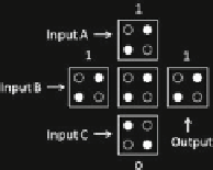
Fig. 4.
A QCA majority voter
MA
;
B
;
C
ð
Þ ¼
AB
þ
AC
þ
BC
ð
1
Þ
MA
;
B
;
0
ð
Þ
AB
þ
B
0
þ
A
0
¼
AB
ð
2
Þ
MA
;
B
;
1
ð
Þ
AB
þ
B
1
þ
A
1
¼
AB
þ
A
þ
B
¼
A
þ
B
ð
3
Þ
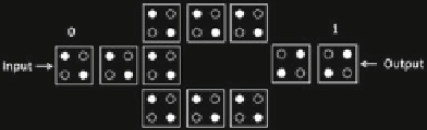
In a QCA inverter, shown in Fig.
5
, the signal that comes in from the input cell
separates into two parallel paths. Cells placed at the output at an orientation of 45 to
these parallel paths are used to change the polarity of the incoming signal.
With implementations of AND, OR and NOT logic, any Boolean logic function
can be constructed using majority voters and inverters. However, such implementa-
tions may not lead to optimal results in terms of the number of logic gates or the
number of logic levels.
2.4
Graph and Subgraph
A graph G consists of a set of vertices represented by V(G), a set of edges represented
by E(G), and an incidence function W
G
that associates each edge to a pair of (not
necessarily
distinct)
vertices.
For
example,
a
graph
G = (V(G),
E(G))
can
be
described by Eq. (
4
).
9
=
V
ðÞ¼
u
;
v
;
w
;
x
;
y
;
f g
E
ðÞ¼
a
;
b
;
c
;
d
;
e
;
f
;
f g
W
G
ðÞ¼
w
f
; W
G
ðÞ¼
w
f
; W
G
ðÞ¼
u
fg
; W
G
ðÞ¼
u
fg
W
G
ðÞ¼
v
fg
; W
G
ðÞ¼
w
f
; W
G
ðÞ¼
z
fg
ð
4
Þ
;
By using points to indicate vertices and using lines to indicate the edges, a
graphical representation for graph G is shown in Fig.
6
. The shape of the graph is not
unique since the positions of the points and the shapes of the lines usually have no
significance.
Fig. 5.
Circuit diagram of an inverter

Search WWH ::

Custom Search