Information Technology Reference
In-Depth Information
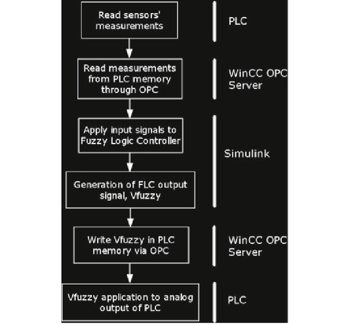
Fig. 12.7
Flowchart of the communication between WinCC, Simulink and PLC
Read blocks. The same treatment is performed with the data calculated by the PLC
program and accumulated in its memory. These signals constitute the FLC inputs.
Such a controller applies the defined control rules to the fuzzyfied inputs to generate
the output. Afterwards, this signal is defuzzyfied. The obtained value is written in the
PLC memory by the WinCC OPC Server using the OPC Write block of Simulink.
The PLC carries out the conditioning of the signal Vfuzzy and transfers it to the
analog output connected to the DC-DC converter of the electrolyzer.
The PLC memory positions associated to both input and output signals are
addressed in the configuration step of the variables of the OPC Server, as can be
seen in Fig.
12.8
. For example, averaged irradiance is read in the address defined as
DB 3 DBD 4, this is, in the data block number 3, DB 3, in the fourth position with
double word size, DBD 4. In the same way, the output signal, Vfuzzy, is located in
the position addressed as DB 9, DBD 0.
The configured blocks of Simulink access to real-time process variables and the
FLC regulates the electrolyzer operating point.
Search WWH ::

Custom Search