Information Technology Reference
In-Depth Information
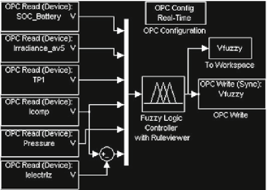
Fig. 12.6
Simulink block diagram of fuzzy control with OPC link scheme
for hydrogen production. The most favorable scenario takes place when there is
available capacity for hydrogen storage, the battery SOC is high, the irradiance is
high and themodule temperature is low. For the rest of situations, the controller output
adapts the hydrogen generation to both the energy availability and the technological
conditions.
It is worth to highlight that the compromise current is only used as threshold. To
this respect, if its value belongs to the subset
Low
, the output signal takes a small
value to reduce, or even stop, the hydrogen generation. The same behavior has been
defined if the bottle pressure is in the partition
High
of such a variable.
Figure
12.6
contains the block diagram of the real-time control system
implemented in Simulink. It consists of three subsystems: OPC Read blocks for
acquisition of input signals, fuzzy controller block for control signal generation and
OPC Write block for real-time writing on PLC memory. The communications para-
meters are defined with the OPC Configuration block, so Simulink acts as OPC
client.
12.4 WinCC, Simulink and PLC Integration
Figure
12.7
shows the sequence of operations from the reading of sensors connected
to the PLC until the generation of the output, Vfuzzy. The read values are stored
in data blocks in the PLC memory. The OPC Server of WinCC flexible Runtime
allows the access to these memory positions from Simulink by means of the OPC
Search WWH ::

Custom Search