Environmental Engineering Reference
In-Depth Information
T
n
Region 1
Region 2
Region 3
T
N
Region 2
Region 3
β
max
Region 1
Ω
Ω
Ω
N
Ω
β
0
min
lim
lim
Rotational speed
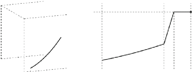
Fig. 4.5 Typical torque-rotational speed curve for a variable-speed variable-pitch wind turbine
proposals. In one of them, two different controllers for low and high wind speeds
together with a switching strategy are designed (see for example, [
8
,
9
]). Simple
controllers can be used in each region at the cost of a bumpless or anti-windup
compensation to reduce undesirable transients in the transition region. The other
approach consists of just one control law (generally nonlinear) covering the whole
operating envelope (see for example, [
2
,
5
]). This approach yields more complex
controllers, hence requiring more advanced control techniques. Furthermore, these
controllers are usually more conservative and quite complex to implement.
The control scheme covering the entire operating range presented in this
chapter is based on the first approach. It is sketched in Fig.
4.6
. As previously
mentioned, the generator torque follows the law in Eq.
4.7
below rated wind
speeds. This control law is implemented as a look-up table, the LUT block in
Fig.
4.6
. While the rotational speed evolves well below rated (X
N
), the pitch angle
remains saturated at its lower limit b
o
. Only after speed reaches X
N
or approaches
it fast enough, the pitch control becomes active. This pitch control is designed here
using H
?
optimal control tools. A gain scheduling technique is used to deal with
the nonlinearity of the aerodynamic torque. In addition, anti-windup compensation
is also included to smooth the transients in the transition region. This compen-
sation is only active when the pitch angle saturates in order to recover optimally
and softly the non saturated loop condition. The damping filter is commonly added
to increase the damping of the drive-train oscillation mode. This filter is active in
the three regions and it must be considered when the pitch controller is designed.
Figure
4.7
depicts the coefficients B
r
, k
V
and k
b
as functions of wind speed over
the operational wind speed range of the 5 MW wind turbine [
6
]. In particular, the
intrinsic damping B
r
and pitch gain k
b
are of special interest since they affect
the stability and performance of the closed loop system. To compensate for the
nonlinearity in the pitch action, the inverse of the coefficient k
b
(k
-1
) is inserted in
the loop. Besides, the intrinsic damping B
r
is considered an uncertain parameter
instead of a nonlinear function of the operating point. In this way, by canceling the
nonlinearity in k
b
and covering with uncertainty the nonlinearity in B
r
, the