Environmental Engineering Reference
In-Depth Information
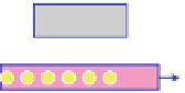
Fig. 10 Device structures of OPVs featuring Ag NPs. a The NPs were fabricated using an
electrochemical method, which controlled their the size and density well [
46
]. b Structure of a
device incorporating a thin Ag film deposited onto an ITO-coated glass substrate. Inset: Field-
emission SEM micrograph of a representative 2-nm-thick Ag layer on ITO [
47
]
(a)
Al
Al
(b)
Ca
Ca
PEDOT:PSS
P3HT:PCBM
P3HT:PCBM
PEDOT:PSS
Au NPs
PEDOT:PSS
Au NPs
Au NPs
ITO
ITO
Glass
Glass
Fig. 11 a Structure of a device featuring Ag NPs and the method of preparation of the buffer
solution containing Au NPs. b Absorption spectra of a Au NP solution and of Au NPs embedded in
PEDOT:PSS. Inset: SEM image of a PEDOT:PSS film prepared with Au NPs blended in the matrix,
revealing the uniform distribution of the Au NPs (white dots) in the PEDOT:PSS layer [
48
,
49
]
2.2 ± 0.1 % after incorporating a 1- or 2-nm-thick layer of plasmon-active Ag
NPs. The PCE decreased slightly upon increasing the size of the Ag NPs.
In addition to Ag NPs, gold (Au), another noble metal, is also a promising
candidate for inducing LSPR phenomena. For example, our group has reported a
solution-processable approach for incorporating Au NPs into OPVs; this process
involved the simple blending of Au NPs and PEDOT:PSS solutions (Fig.
11
a) [
48
,
49
]. A plasmonic layer, consisting of Au NPs and PEDOT:PSS, was readily
formed after spin-coating of the mixture. The size of the NPs (ca. 40 nm) was
selected intentionally so that their SP peak matched the absorption wavelength of
P3HT. The UV-Vis spectrum in Fig.
11
b reveals that the resonance peak of the Au
NPs in solution appeared near 550 nm. The standard device prepared without Au
NPs exhibited a PCE of 3.57 %. The value of J
sc
increased after incorporation of


Search WWH ::

Custom Search