Environmental Engineering Reference
In-Depth Information
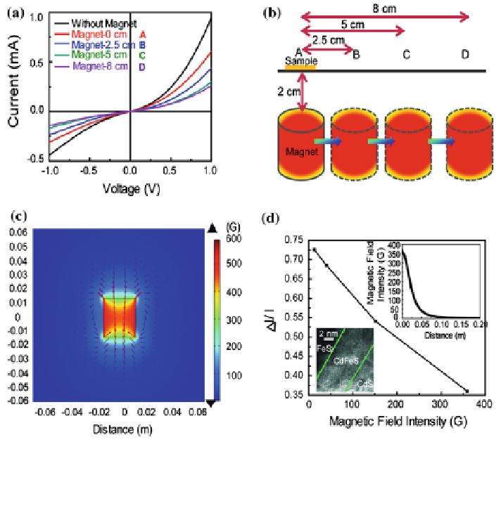
Fig. 21 a J-V curves showing dependence on magnet placement. b Schematic of experiment ran
to obtain J-V curves. c Simulated image of magnetic field intensity. d Relative current intensity
dependent on magnet distance. Inset is TEM image showing interfacial layer. Reprinted with
permission from [
63
]
References
1. Zweibel K, Mason J, Fthenakis V (2008) By 2050 solar power could end US dependence on
foreign oil and slash greenhouse gas emissions. Sci Am 298(1):64-73
2. Green M (2000) Power to the people: sunlight to electricity using solar cells. University of
New South Wales Press, Sydney
3. Wadia C, Wu Y, Gul S, Volkman SK, Guo J, Alivisatos AP (2009) Surfactant-assisted
hydrothermal
synthesis
of
single
phase
pyrite
FeS2
nanocrystals.
Chem
Mater
21(13):2568-2570
4. Ennaoui A, Fiechter S, Pettenkofer C, Alonsovante N, Buker K, Bronold M et al (1993) Iron
disulfide for solar-energy conversion. Sol Energy Mater Sol Cells 29(4):289-370. PubMed
PMID: WOS:A1993LH67000001 (English)
5. Altermatt PP, Kiesewetter T, Ellmer K, Tributsch H (2002) Specifying targets of future
research in photovoltaic devices containing pyrite (FeS2) by numerical modelling. Sol
Energy Mater Sol Cells 71(2):181-195
Search WWH ::

Custom Search